تقنية رفع اسقف الخزانات
Roof air rising
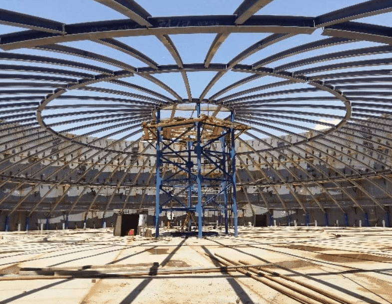
Assembling procedure of the roof and suspended deck
After installation of the outer bottom plate simultaneously with the installation of the outer shell, deck plates installed on bottom plates and after checking their dimension, welding procedure initiated. After completion of the deck assembly and welding, central ring was assembled on a temporary column and by means of temporary support around the internal circumference of the shell, ring girder and all of rafters and gusset plates were erected and welded. Afterwards, roof plate’s installation commenced according to sketch plate erection and then roof plates welded to each other. At the next step, hanger clips on the rafter, girder and stiffener of deck, were installed and finally suspended deck hanger was erected (see fig.1-4). Also six nozzles were cut and then welded on roof plates on proper positions.


Necessary accessories for air rising
In order to perform air rising correctly, some preliminaries shall be implemented comprising installation and welding of compression bar at top of the last shell course, installation of levelling cables, sealing system, preparing and installation of manometers, installation of blowers and etc. Fig 5 shows a schematic view of all necessary items that shall be supplied prior to starting the operation.

Leveling cables
After installation, fit-up and welding of the compression bars, sixteen temporary supporting arms were erected on compression bar for installation of levelling cables. Cable levelling system was installed to assist roof stabilization as it travelled from bottom of the tank to its final top position. The end of levelling cables were connected to supporting arms and annular plates of outer bottom plates by drilling the roof plate (see fig 6-7). Each wire pulled toward the bottom plate (500 mm away from the shell of the tank) and stretched by each turnbuckle until the tension reached to 1,000 kgf, the tension load was checked by using resonant frequency method, according to the following formula:


Arrangement of air blowers
The necessary air for operation was supplied by two blowers that were erected on temporary plate of the shell. One of these blowers was main and the second was standby. Standby blower operated by one generator separately (see fig 8).


Sealing system arrangement
To prevent air leakage during air rising process, all the gaps needed be sealed. Thus, a sealing system was designed to prevent escaping of the air between the roof and the shell. In addition, all of positions that were prone the air leakage were identified and sealed using adhesive tape or plaster.
To seal the space between the roof and shell, temporary bent plates were designed and fastened to the end of roof plates. Then, temporary seals consisting of polyethylene sheets and pre-assembled wire mesh were erected on temporary bent plates using nuts and bolts (see fig 9).

Arrangement of measuring equipment
A measuring system for recording the levelness of the roof structure was installed at four positions using four meter tapes along the shell (,, , to control the levelness. All data were measured at the same time. For this purpose, four persons were present on deck plates during lifting the roof. These persons had separate walkie-talkies. Commander should receive data from each person every 5 minutes to record the roof slope. During lifting the roof, maximum tolerance for levelness of the roof was five mm. finally the roof raised successfully without any problem.

Arrangement of manometers
The inside pressure of the tank should be checked during air rising. So three manometers were installed around the tank. The first, near the blowers, the second, on the roof and the third, on the last course of the shell. Three persons checked the inside pressure of the tank using mentioned manometers. According to calculations, inside pressure of the tank was kept at 20 mm H2O.

Preparation for roof fixing work
Necessary tools were arranged for the angular alignment of the roof, such as levers, jacks, jigs, tools and welding equipment around the top of roof for fit-up and welding of roof to compression bar. In addition, ten welders were arranged around the compression bar for fixing and welding the roof to compression bar.
Pre-air rising
Prior to actual rising operation, the pre-air rising of the roof was performed up to 40 cm, Fig 12, to check the following conditions:

- Floating pressure and maintaining pressure.
- Opening ratio of blower damper and current value.
- Slope of the roof, seal gap between temporary roof and outer shell and movement of the roof.
- Sealing condition between roof and shell.
- Preparation of workers.
- Checking the roof balance. In case of witnessing any imbalance, correction was performed by applying some weight on the suspended deck. (Maximum tolerance for roof imbalance was 50 mm).
- The deck plate annular were used to balance the roof of the tank.
- Ensuring that the roof is in its stable state, and also checking the state of sealing material after the roof was put down on the temporary roof support.
Pre–air rising performed successfully, air leakage was identified in some areas and were sealed accordingly with adhesive tape and plaster (see fig 13).

Roof Air rising
Air rising of the roof started and continued as per below procedure:
- Starting two blowers simultaneously.
- Checking the levelness of the roof as it started to rise.
- Slowing down the rising speed at the top 1000 mm of the height.
- Rising stopped at the top 200 mm of the height and rotation, alignment and also the centre of the roof were checked using meter tapes in random points.
- Rising continued slowly until the roof touched the compression bar.
- Foremen checked the entire compression bar along the circumference before starting any pinning of the roof.
- After reaching to final position, the roof was fixed by using lugs and channels that already had been arranged around the tank. Then, compression bar connected to the roof by applying tack welds

fter tack-welding the roof to compression bar and without decreasing the internal pressure, the circumferential welding process started. 10 cm on the area of T joints were left un-welded due to huge air leakage.
- At the final step, the blowers were shut-down and those remaining un-welded areas were welded entirely.
- The fixing jigs, seal and other air rising equipment were removed from the roof plate.
- The holes for the balancing cables on the roof were covered by using the same type plate as the roof and with the dimension of 100×100×10 mm.
Fig 15-18 shows some different views of the roof during the air rising.


Safety considerations prior to air rising
Before initiation of air rising, all necessary items were checked as below:
- Checking all the tools and equipment for air rising
- Generators and air blower inspected prior to air rising process.
- Because of limitation caused by weather condition at rainy days and also maximum wind speed at 14 , weather condition were checked several days before.
- Checking and confirming that all levelling cables were fully installed and connected.
- Checking that the temporary seals for tank were fully installed and taped.
- Ensuring that equal flow rate could be achieved for each blower.


موضوع مهم جدا و سعيدة جدا أنه يوجد شركات مصرية تقوم بهذه الخدمة
ردحذفwww.fepcoegypt.com
https://www.fepcoegypt.com/Tank-Roof-Air-Raising.html